
I'm routing on the edge...
In my last post (Routed Port vs. Switch Virtual Interface (SVI)), I have mentioned a consequence of using routed ports to interconnect access and core switches:
You have to route the traffic on the access switches.
Routing on the network access, the edge of the network, is not a question of performance. It is more of a management issue. Depending on the size of your network, and the number of subnets, you have to deal with lots of routes. And think about the effort, if you add, change or remove subnets from your network. This is not what you want to do with static routes. You need a routing protocol.
The experiment of the week
We have a core switch C1, consisting of two independent switches (C1-1 and C1-2) forming a virtual chassis. S1 and S2 are two switches at the network access. This is a core-edge design. There is no distribution layer. Each switch at the network access has two uplinks: One uplink to C1-1 and one uplink to C1-2. The ports on each end of the links are configured as routed ports.
Please ignore the 40 GbE ports (FGE) between C1-1 and C1-2. These ports are used for the Intelligent Resilient Framework (IRF), which is used to create a virtual chassis.
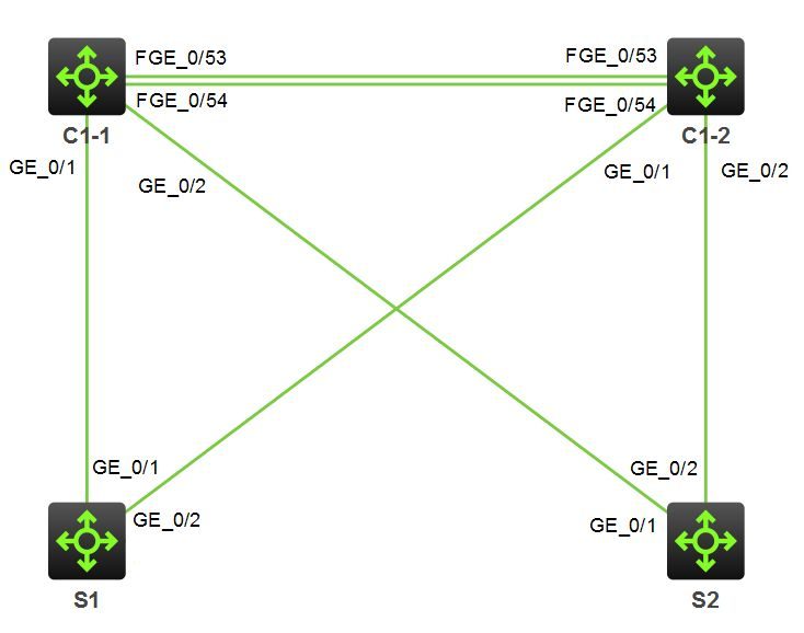
Patrick Terlisten/ vcloudnine.de/ Creative Commons CC0
These are the interfaces on the core switch, that are working in route mode. GE1/0/1 and GE2/0/1 are the uplinks to S1, and GE1/0/2 and GE2/0/2 are the uplinks to S2.
[C1]display interface brief
Brief information on interface(s) under route mode:
Link: ADM - administratively down; Stby - standby
Protocol: (s) - spoofing
Interface            Link Protocol Main IP         Description
GE1/0/1              UP   UP       10.0.0.1
GE1/0/2              UP   UP       10.10.0.1
GE2/0/1              UP   UP       10.1.0.1
GE2/0/2              UP   UP       10.11.0.1
InLoop0              UP   UP(s)    --
Loop0                UP   UP(s)    1.1.1.1
MGE0/0/0             DOWN DOWN     --
NULL0                UP   UP(s)    --
REG0                 UP   -- --
These are the interfaces on the access switch S1, that are working in route mode. GE1/0/1 and GE1/0/2 are the uplinks to C1. As you can see, GE1/0/1 on C1 and GE1/0/1 on S1 belong to the same /30 network. The same applies to GE2/0/1 on C1 and GE1/0/2 on S1. There are also two SVIs, one on VLAN 1 (192.168.1.0/24) and another on VLAN 2 (192.168.2.0/24). These VLANs are used for client connectivity.
[S1]display interface brief
Brief information on interface(s) under route mode:
Link: ADM - administratively down; Stby - standby
Protocol: (s) - spoofing
Interface            Link Protocol Main IP         Description
GE1/0/1              UP   UP       10.0.0.2
GE1/0/2              UP   UP       10.1.0.2
InLoop0              UP   UP(s)    --
Loop0                UP   UP(s)    1.1.1.2
MGE0/0/0             DOWN DOWN     --
NULL0                UP   UP(s)    --
REG0                 UP   -- --
Vlan1                UP   UP       192.168.1.1
Vlan2                UP   UP       192.168.2.1
These are the interfaces on S2, that are working in route mode. GE1/0/1 and GE1/0/2 are the uplinks to C1. The interfaces GE1/0/2 on C1, and GE1/0/1 on S2 belong to the same /30 network. The same applies to GE2/0/2 on C1 and GE1/0/2 on S2. There are also two SVIs, one on VLAN 1 (192.168.10.0/24) and another on VLAN 2 (192.168.20.0/24).
You might wonder, because the same VLAN IDs are used on both access switches. They don’t care, because there is no layer 2 connectivity between these two switches. The only way from S1 to S2 is over the routed links to the core switch.
[S2]display interface brief
Brief information on interface(s) under route mode:
Link: ADM - administratively down; Stby - standby
Protocol: (s) - spoofing
Interface            Link Protocol Main IP         Description
GE1/0/1              UP   UP       10.10.0.2
GE1/0/2              UP   UP       10.11.0.2
InLoop0              UP   UP(s)    --
Loop0                UP   UP(s)    1.1.1.3
MGE0/0/0             DOWN DOWN     --
NULL0                UP   UP(s)    --
REG0                 UP   -- --
Vlan1                UP   UP       192.168.10.1
Vlan2                UP   UP       192.168.20.1
Now let’s have a look at the Open Shortest Path First (OSPF) routing protocol.
Single Area OSPF
The Open Shortest Path First (OSPF) routing protocol is an interior gateway protocols (IGP), and also a link-state routing protocol. The calculation of the shortest path for each route is based on Dijkstra’s algorithm. I don’t want to annoy you with details. Take a look at the Wikipedia article for OSPF.
The simplest OSPF setup is a “Single Area OSPF”. This is an OSPF configuration, which has only a single area. This is the area 0, or the backbone area.
The configuration on the core switch looks like this:
[C1]ospf 1
[C1-ospf-1]display this
#
ospf 1
 area 0.0.0.0
  network 1.1.1.1 0.0.0.0
  network 10.0.0.0 0.255.255.255
#
The networks, that should be associated with this area, are specified with a wildcard mask. The wildcard mask is the opposite of the subnet mask. The wildcard mask 0.255.255.255 corresponds to the subnet mask 255.0.0.0. Because I have used multiple /30 subnets at the core switch, I can summarize them with a single entry for 10.0.0.0.
The same configuration applies to the access switches S1 and S2.
[S1]ospf 1
[S1-ospf-1]display this
#
ospf 1
 area 0.0.0.0
  network 1.1.1.2 0.0.0.0
  network 10.0.0.0 0.255.255.255
  network 192.168.0.0 0.0.255.255
#

[S2]ospf 1
[S2-ospf-1]display this
#
ospf 1
 area 0.0.0.0
  network 1.1.1.3 0.0.0.0
  network 10.0.0.0 0.255.255.255
  network 192.168.0.0 0.0.255.255
#
With this simple configuration, the switches will exchange their routing information. They will synchronize their link-state databases, and they will be fully adjacent. If a link-state change occurs, OSPF will handle this.
The core switch has two links to each access switch. The router ID represents the access switches. 1.1.1.2 is a loopback interface IP address on S1, 1.1.1.3 is a loopback interface IP address on S2.
<C1>display ospf peer

         OSPF Process 1 with Router ID 1.1.1.1
               Neighbor Brief Information

 Area: 0.0.0.0
 Router ID       Address         Pri Dead-Time  State             Interface
 1.1.1.2         10.0.0.2        1   37         Full/DR           GE1/0/1
 1.1.1.3         10.10.0.2       1   36         Full/DR           GE1/0/2
 1.1.1.2         10.1.0.2        1   38         Full/DR           GE2/0/1
 1.1.1.3         10.11.0.2       1   35         Full/DR           GE2/0/2
The same applies to the access switches, in this case S1. The access switches have also two active links to the core switch.
<S1>dis ospf peer

         OSPF Process 1 with Router ID 1.1.1.2
               Neighbor Brief Information

 Area: 0.0.0.0
 Router ID       Address         Pri Dead-Time  State             Interface
 1.1.1.1         10.0.0.1        1   31         Full/BDR          GE1/0/1
 1.1.1.1         10.1.0.1        1   32         Full/BDR          GE1/0/2
If one of the links fail, the access switch has another working link to the core switch, and OSPF will recalculate the shortest paths, taking the link-state change (link down between core and an access switch) into account.
This is the OSPF routing table of the core switch, based on the example above.
<C1>display ospf routing

         OSPF Process 1 with Router ID 1.1.1.1
                  Routing Table

 Routing for network
 Destination        Cost     Type    NextHop         AdvRouter       Area
 192.168.10.0/24    2        Stub    10.10.0.2       1.1.1.3         0.0.0.0
 192.168.10.0/24    2        Stub    10.11.0.2       1.1.1.3         0.0.0.0
 10.10.0.0/30       1        Transit 0.0.0.0         1.1.1.3         0.0.0.0
 10.11.0.0/30       1        Transit 0.0.0.0         1.1.1.3         0.0.0.0
 10.0.0.0/30        1        Transit 0.0.0.0         1.1.1.2         0.0.0.0
 10.1.0.0/30        1        Transit 0.0.0.0         1.1.1.2         0.0.0.0
 1.1.1.1/32         0        Stub    0.0.0.0         1.1.1.1         0.0.0.0
 1.1.1.2/32         1        Stub    10.0.0.2        1.1.1.2         0.0.0.0
 1.1.1.2/32         1        Stub    10.1.0.2        1.1.1.2         0.0.0.0
 1.1.1.3/32         1        Stub    10.10.0.2       1.1.1.3         0.0.0.0
 1.1.1.3/32         1        Stub    10.11.0.2       1.1.1.3         0.0.0.0
 192.168.20.0/24    2        Stub    10.10.0.2       1.1.1.3         0.0.0.0
 192.168.20.0/24    2        Stub    10.11.0.2       1.1.1.3         0.0.0.0
 192.168.1.0/24     2        Stub    10.0.0.2        1.1.1.2         0.0.0.0
 192.168.1.0/24     2        Stub    10.1.0.2        1.1.1.2         0.0.0.0
 192.168.2.0/24     2        Stub    10.0.0.2        1.1.1.2         0.0.0.0
 192.168.2.0/24     2        Stub    10.1.0.2        1.1.1.2         0.0.0.0

 Total nets: 17
 Intra area: 17  Inter area: 0  ASE: 0  NSSA: 0
What if I add a new subnet on S1? Let’s create a new VLAN and add a SVI to it (VLAN 3 and 192.168.3.1).
[S1]dis int brief
Brief information on interface(s) under route mode:
Link: ADM - administratively down; Stby - standby
Protocol: (s) - spoofing
Interface            Link Protocol Main IP         Description
GE1/0/1              UP   UP       10.0.0.2
GE1/0/2              UP   UP       10.1.0.2
InLoop0              UP   UP(s)    --
Loop0                UP   UP(s)    1.1.1.2
MGE0/0/0             DOWN DOWN     --
NULL0                UP   UP(s)    --
REG0                 UP   -- --
Vlan1                UP   UP       192.168.1.1
Vlan2                UP   UP       192.168.2.1
Vlan3                UP   UP       192.168.3.1
Without touching the OSPF configuration, the core switch C1, and the other access switch S2, added routes to this new subnet.
<C1>display ospf routing

         OSPF Process 1 with Router ID 1.1.1.1
                  Routing Table

 Routing for network
 Destination        Cost     Type    NextHop         AdvRouter       Area
 192.168.3.0/24     2        Stub    10.0.0.2        1.1.1.2         0.0.0.0
 192.168.3.0/24     2        Stub    10.1.0.2        1.1.1.2         0.0.0.0
 192.168.10.0/24    2        Stub    10.10.0.2       1.1.1.3         0.0.0.0
 192.168.10.0/24    2        Stub    10.11.0.2       1.1.1.3         0.0.0.0
 10.10.0.0/30       1        Transit 0.0.0.0         1.1.1.3         0.0.0.0
 10.11.0.0/30       1        Transit 0.0.0.0         1.1.1.3         0.0.0.0
 10.0.0.0/30        1        Transit 0.0.0.0         1.1.1.2         0.0.0.0
 10.1.0.0/30        1        Transit 0.0.0.0         1.1.1.2         0.0.0.0
 1.1.1.1/32         0        Stub    0.0.0.0         1.1.1.1         0.0.0.0
 1.1.1.2/32         1        Stub    10.0.0.2        1.1.1.2         0.0.0.0
 1.1.1.2/32         1        Stub    10.1.0.2        1.1.1.2         0.0.0.0
 1.1.1.3/32         1        Stub    10.10.0.2       1.1.1.3         0.0.0.0
 1.1.1.3/32         1        Stub    10.11.0.2       1.1.1.3         0.0.0.0
 192.168.20.0/24    2        Stub    10.10.0.2       1.1.1.3         0.0.0.0
 192.168.20.0/24    2        Stub    10.11.0.2       1.1.1.3         0.0.0.0
 192.168.1.0/24     2        Stub    10.0.0.2        1.1.1.2         0.0.0.0
 192.168.1.0/24     2        Stub    10.1.0.2        1.1.1.2         0.0.0.0
 192.168.2.0/24     2        Stub    10.0.0.2        1.1.1.2         0.0.0.0
 192.168.2.0/24     2        Stub    10.1.0.2        1.1.1.2         0.0.0.0

 Total nets: 19
 Intra area: 19  Inter area: 0  ASE: 0  NSSA: 0

<S2>display ospf routing

         OSPF Process 1 with Router ID 1.1.1.3
                  Routing Table

 Routing for network
 Destination        Cost     Type    NextHop         AdvRouter       Area
 192.168.3.0/24     3        Stub    10.10.0.1       1.1.1.2         0.0.0.0
 192.168.3.0/24     3        Stub    10.11.0.1       1.1.1.2         0.0.0.0
 192.168.10.0/24    1        Stub    0.0.0.0         1.1.1.3         0.0.0.0
 10.10.0.0/30       1        Transit 0.0.0.0         1.1.1.3         0.0.0.0
 10.11.0.0/30       1        Transit 0.0.0.0         1.1.1.3         0.0.0.0
 10.0.0.0/30        2        Transit 10.10.0.1       1.1.1.2         0.0.0.0
 10.0.0.0/30        2        Transit 10.11.0.1       1.1.1.2         0.0.0.0
 10.1.0.0/30        2        Transit 10.10.0.1       1.1.1.2         0.0.0.0
 10.1.0.0/30        2        Transit 10.11.0.1       1.1.1.2         0.0.0.0
 1.1.1.1/32         1        Stub    10.10.0.1       1.1.1.1         0.0.0.0
 1.1.1.1/32         1        Stub    10.11.0.1       1.1.1.1         0.0.0.0
 1.1.1.2/32         2        Stub    10.10.0.1       1.1.1.2         0.0.0.0
 1.1.1.2/32         2        Stub    10.11.0.1       1.1.1.2         0.0.0.0
 1.1.1.3/32         0        Stub    0.0.0.0         1.1.1.3         0.0.0.0
 192.168.20.0/24    1        Stub    0.0.0.0         1.1.1.3         0.0.0.0
 192.168.1.0/24     3        Stub    10.10.0.1       1.1.1.2         0.0.0.0
 192.168.1.0/24     3        Stub    10.11.0.1       1.1.1.2         0.0.0.0
 192.168.2.0/24     3        Stub    10.10.0.1       1.1.1.2         0.0.0.0
 192.168.2.0/24     3        Stub    10.11.0.1       1.1.1.2         0.0.0.0

 Total nets: 19
 Intra area: 19  Inter area: 0  ASE: 0  NSSA: 0
Pretty cool, isn’t it?
Any downsides?
This is only an example with a single core switch and two access switches. OSPF can be pretty complex, if the size of the network increases. The Dijkstra’s algorithm can be really CPU intensive, and the size of the link-state databases (LSDB) increase with adding more routers and networks. For this reason, larger networks have to be divided into separate areas. It depends on the network size and the CPU/ memory performance of your switches/ routers, but a common practice is a maximum of up to 50 switches/ routers per area. If you have unstable links, the area should be smaller, because each link-state change is flooded to all neighbors and consumes CPU time.
You need a good subnet design, otherwise you have to touch your OSPF configuration too often. You should be able to summarize subnets.
Conclusion
Routing at the network access is nothing for small networks. There are better designs for small networks. But if your network has a decent size, routing at the edge of the network can offer some benefits. Instead of working with SVIs and small transfer VLANs, a routed port is more simple to implement. Routed links can also have a shorter convergence delay, and you can reduce the usage of Spanning Tree Protocol to a minimum.